

How To Calculate Cooling Tower Makeup Water
Applying mass and free energy balance calculations yields critical operating insight
Cooling towers are an of import unit of measurement operation in chemical procedure industries (CPI) operations. Applying mass and free energy residue calculations enables process engineers to evaluate evaporation loss, blowdown and makeup-water requirements, and to evaluate the performance of the cooling tower. In this article, an illustrative study showcases an induced-typhoon cooling tower and describes several cardinal parameters — range, approach and efficiency — and their significance. Two methods are discussed to gauge evaporation loss. Requirements for blowdown and makeup water are also detailed.
Cooling tower performance
The cooling of procedure streams and condensation of vapors are important functions in CPI operations. The apply of a cooling tower is the near common way of extracting waste material estrus in CPI operations, and water is the nearly commonly used coolant to remove waste rut in the majority of such operations. A typical large petroleum refinery that processes 40,000 metric tons (chiliad.t.) of crude oil per 24-hour interval requires 80,000 one thousand 3 /h of cooling h2o. This is roughly equivalent to 25 barrels of water for every butt of crude oil processed [ 1].
In a cooling tower, the hot h2o stream (typically called the cooling h2o return) is introduced downwards through spray nozzles into fills inside the tower. There are different types of fills — splash, trickle and film — that are aimed at creating more than surface expanse, to maximize contact between the hot water stream and air. Equally air rises inside the tower, it receives the latent heat of vaporization from the water, and thus the water is cooled.
As a dominion of thumb, for every 10°F (v.5°C) of water cooling, 1% total mass of water is lost due to evaporation. The humidity level of the up-flowing air stream increases, and once information technology leaves the tower the air stream is most saturated. The temperature profile of the h2o and the wet-bulb temperature of the air along the superlative of a typical cooling tower is shown in Effigy one.
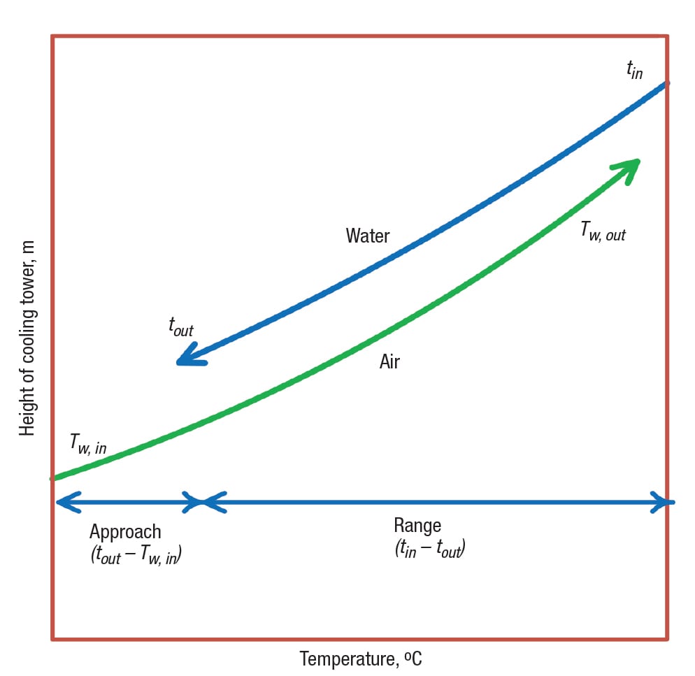
FIGURE one. Shown here is the typical variation of the h2o temperature and the moisture-seedling temperature of the air stream as the hot water inlet stream flows downwardly from the top of the cooling belfry and the air stream flows up along the pinnacle of the cooling tower
The cooled water is nerveless in the sump (or basin) of the cooling tower, and it is typically pumped to the plant as the cooling-water-supply (CWS) stream. Subsequently extracting heat from the process units, this stream is returned to the cooling tower, equally the cooling-h2o-return (CWR) stream. The heat load extracted from the process unit of measurement is finally released to the environs in the cooling tower. A cooling tower is designed to remove the total heat load that is extracted from the plant by reducing the CWR temperature to the CWS temperature.
Case study
The CWR line from the process unit enters an industrial cooling tower at 45°C and leaves at 33°C, as shown in Figure 2. The tower has three cells, each operating at 2,500 chiliad iii /h of water period. The full flow 7,500 m 3 /h is measured at the CWR line. The dry-seedling temperature and wet-bulb temperature of the inlet air are measured every bit 30.3°C and 29°C, respectively. The dry-bulb temperature of the exit air is 41.five°C, and it is assumed to be 100% saturated. This case study is aimed at computing the unknown variables — that is, evaporation loss, air period through the belfry, blowdown flow, and the required makeup water flow. First, the important parameters — approach, range and efficiency — are detailed.
Approach. The approach is defined equally the difference between the h2o temperature at the tower outlet ( t out) and the wet-bulb temperature of the inlet air ( T due west,in). The approach represents the cooling tower capability. In full general, the larger the tower, the smaller is the arroyo. In this case written report, the approach is four°C.
Theoretically, the extent of maximum possible cooling that could exist accomplished through a cooling tower would exist to produce a stream that is at the wet-bulb temperature of the ambient air. Nevertheless, to achieve this theoretical maximum, the tower would demand to have infinite height. So the practical limit of the CWS temperature is generally considered to be 4°C in a higher place the wet-seedling temperature of ambience air. For blueprint purposes, the worst scenario — that is, the summer season wet-bulb temperature — needs to exist considered.
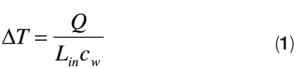
Range (ΔT) . The range is the difference betwixt the water temperatures at the inlet and the outlet of the cooling belfry (t in – t out). In this instance, the range is 12°C. The range does not represent the cooling tower capability; rather, the range is based on the cooling-water circulation flowrate ( Fifty in), and the sum of the estrus loads taken from the heat exchangers in the process unit of measurement ( Q), and it is not related to the size or capability of the cooling tower. On the other hand, an increase in range will cause an increase in arroyo, if all other atmospheric condition are not changed. The range is shown in Equation (i):
Cooling belfry efficiency () . The cooling tower efficiency is the ratio of actual cooling (range) to the theoretically possible maximum cooling (that is, when the arroyo is zero), as shown in Equation (2):
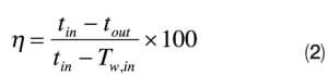
Theoretically, an approach of cipher ways the tower is 100% efficient. Industrial cooling towers typically have an approach temperature betwixt 4° and eight.5°C, and an efficiency betwixt 70 and 75% [ two]; in this case, the efficiency is 75%.
Evaporation loss and air needs
Method one. The evaporation loss and air period requirement through the tower can exist evaluated by solving the mass and energy residuum equations simultaneously.
Use Equation (iii) to utilize a mass balance for the entire department of belfry. As shown in Equation (3), the amount of h2o evaporated ( e 50) in the down-pouring liquid is the difference between the inlet liquid flow ( Fifty in) and the sum of the outlet liquid flow (L out) and the migrate loss ( d L). Information technology is equal to the difference of moisture content of air across the belfry.
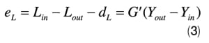
Where:
Thousand' = the quantity of dry air period (which remains the same at the inlet and outlet air streams), kg of dry air
Y = absolute humidity, kg water/kg dry air/h
The subscripts in and out refer to the entry and exit locations.
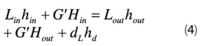
The overall energy balance is given by Equation (4):
Where:
h = the liquid enthalpy, kJ/kg water
H = the moist air enthalpy, kJ/kg dry air
Substituting L out from Equation (3) into Equation (4), and assuming the enthalpy of the migrate water h d is h out, and simplifying Equation (four), one gets Equation (5):
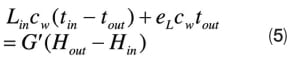
Solving both mass and heat residuum equations [Equations (3) and (5)] simultaneously, the evaporation loss ( e Fifty) and the dry-air requirement ( G') are estimated as 132,000 kg/h and G' = four,699,850 kg dry air/h, respectively.
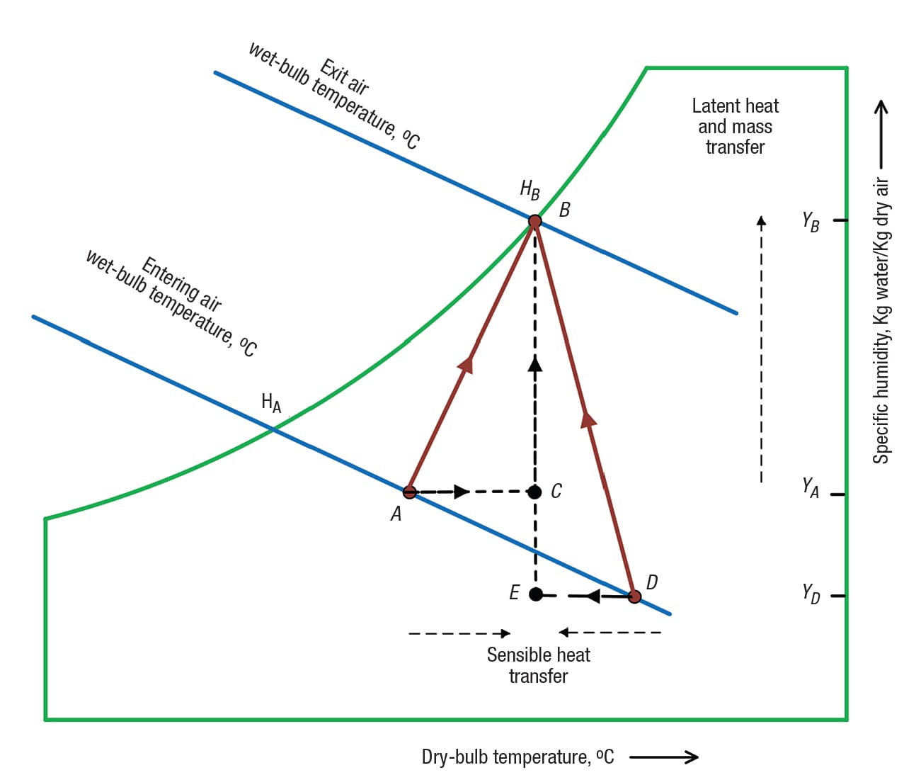
FIGURE 3. In this psychrometric nautical chart, the relevant process condition from the case history is marked as vector AB
 Method ii. Depending on the temperature of the inlet air (whether it is hot or common cold), the air can be either heated or cooled equally information technology travels forth the pinnacle of a cooling tower. In the psychrometric chart shown inFigure 3, the entering status of the air is denoted by bespeak A, and the exit air (which is completely saturated with water) is denoted by point B. The enthalpy difference of dry air is ( H A –H B). The vector AB is the sum of the ii components. The horizontal component Air-conditioning represents the sensible heating of air, and the vertical component CB is the latent heating of air. In a cooling tower, it is also possible to cool the air if the inlet air condition is at D[ three]. At betoken D, the air is hot and dry, when compared to the air at signal A.
The component DE is the sensible air cooling, and the component EB is the latent heating of air. The net oestrus received by the air is the deviation between the latent air heating and the sensible air cooling.
In the case of the AB process, the dry-bulb temperature of the air is increased at the exit — that is, the exit air becomes hot compared to the inlet air. But in the example of DB, the dry-seedling temperature of air is decreased and thus the air is cooled at the get out. In both cases, the moisture-seedling temperature of the exit air will always exist increased compared with that of the inlet air. And so, the water flowing through the cooling tower can be cooled by unsaturated air, irrespective of whether the air is hot or cold.
In this instance report, from the field measurements of DBT and WBT, the psychrometric backdrop, such as accented humidity, saturation humidity and moist air enthalpy for the inlet air and the outlet air, could be evaluated. The inlet air is marked as point A, and the outlet air is marked equally point B in the psychrometric chart. Another hypothetical bespeak C is marked in such a way that it has a dry-bulb temperature similar to point B and accented humidity similar to point A. It must be noted that the betoken C is a hypothetical and does not represent to whatsoever location in the cooling belfry; the point C is marked on the chart to encounter the horizontal and vertical component of vector AB. Moist air enthalpy for point C is calculated.
The total heat gained past the air ( H B –H A) has ii components: the latent heat transfer ( H B –H C), and the sensible estrus transfer ( H C –H A). The ratio of latent heat transferred ( e L o) to the total heat released from the water side is shown by on the left in the Equation (6), and this expression is numerically equal to the ratio of latent heat added to the dry air to the total rut gained by the air, which is shown on the right side in the Equation (6):
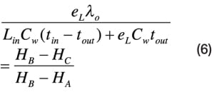
From Equation (half dozen), due east L is calculated as 132,000 kg/h. It is to be noted that in this method, the dry out air flow ( M') is non required. One time e Fifty is evaluated, Grand' is estimated from the mass balance equation [(Equation (3)]. The split of latent heat transfer and sensible air heating in this case is virtually 85% and 15%, respectively.
Makeup water and blowdown
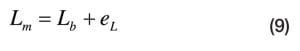
Makeup water ( L g) is added to the sump to recoup for the h2o losses in the circuit. The water losses include evaporation loss ( e L), migrate loss ( d L), blowdown ( L b), and other leakage losses ( O L) in the organization, such as losses from the pump seal, pipe leak, washdown water and filter backwash.
![]()
Drift loss. Small droplets that are entrained past the upward-flowing air stream are nerveless in a mist eliminator, where they accrue to form larger drops that are eventually returned to the fill. In general, very little water in the course of droplets is carried along with the air, just those aerosol do results in water loss, called drift loss or windage loss. This drift water typically contains dissolved solids and may cause stain, corrosion or impairment to nearby buildings and structures. Drift loss is usually about 0.ane–0.3% of the apportionment water charge per unit ( L in).
To recoup for the evaporation loss and drift loss, additional makeup water is added. Since the makeup water typically contains dissolved solids, these solids are typically left behind in the sump water every bit the water evaporates in the cooling tower. Meanwhile, since the cooling water is a very constructive air scrubber, dust and droppings present in the upward-flowing air is washed out past down-pouring water and collects in the sump. As solids accumulate in the sump, they increase the potential for scale corrosion and biological fouling in the cooling-water circuit. By taking small amounts of water continuously from the cooling tower circuit (blowdown), the concentration of dissolved solids in the cooling water tin exist reduced below the upper limit of the acceptable range, in gild to meet the cooling-water quality specification of the plant.
Blowdown. At that place are two ways to remove the blowdown — equally hot blowdown and common cold blowdown (Figure ii). Hot blowdown refers to the continuous removal of h2o in the cooling-water-render line to the effluent. Since the water is hot at this location, hot blowdown may not exist acceptable in some applications due to potential environmental touch; in other cases, it is desired, since it reduces throughput to the cooling tower and increases overall cooling functioning.
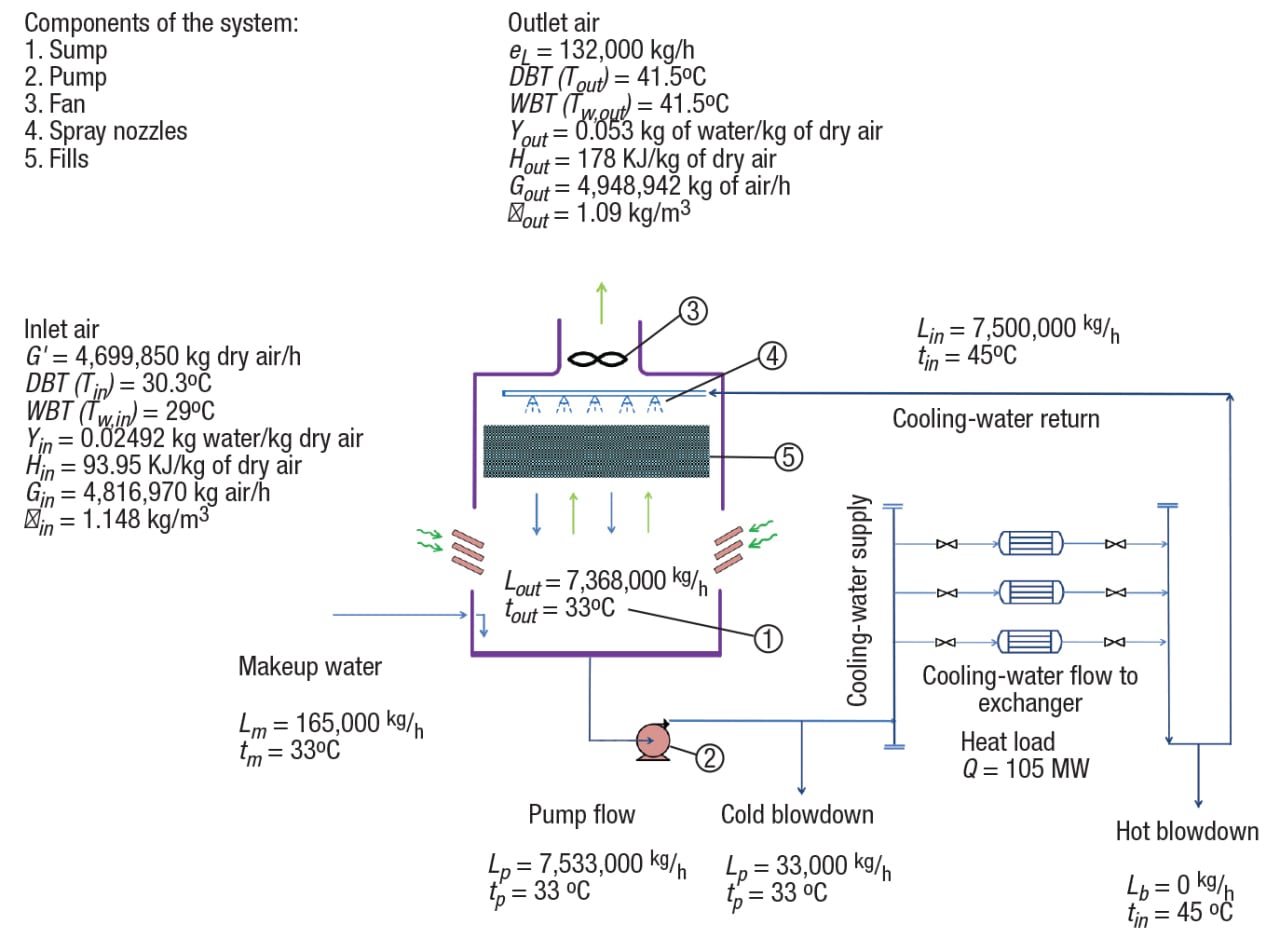
FIGURE 2. This schematic diagram depicts the parameters of the case study cooling tower system.
Note: All 3 cells and three fans are lumped together and shown as a single unit
Cold blowdown refers to the continuous removal of water from the cooling-water pump outlet to the effluent [ iv]. Migrate loss and any leakage loss from the system are also considered as blowdown, since these streams contain dissolved solids (but such losses are unintentional).
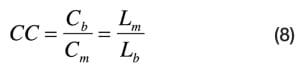
The amount of water blowdown is established by calculating the cycle of concentration ( CC), which is divers as the ratio between the amount of solids dissolved (more often than not chlorides) in the blowdown and in the makeup water, using Equation (8):
Assuming migrate loss and leakage losses are negligible, and solving the water-balance shown below in Equation (9):
The dissolved-solids balance shown below in Equation (10), the blowdown is calculated using Equation (11):
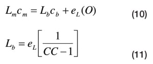
Farther, the corporeality of makeup h2o needed is estimated, including drift, using Equation (12):
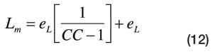
The required makeup h2o mainly depends on evaporation loss and the CC calculated above. It is to be noted from Equation (eleven) that the minimum value of CC to be considered is 2, which requires blowdown to be at the aforementioned amount of water every bit the amount lost in evaporation. Whatsoever effort to reduce the CC below two results in a pregnant amount of makeup water, as shown in Figure 4.
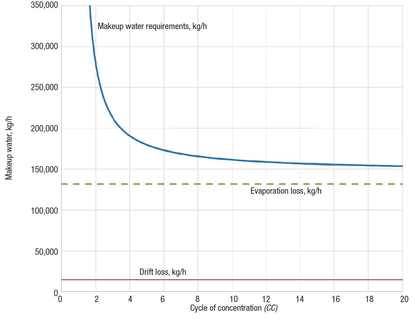
Effigy 4. Makeup h2o requirements versus the cycle of concentration are shown here
Higher CCmeans that C m tends to zero (indicating good quality of the makeup water). Only, this is achieved at the cost of water handling of the source water. A typical cycle of concentration ( CC= 5) is considered in this case study for the optimum requirement. Based on the evaporation loss and cycle of concentration, cold blowdown and makeup water are calculated using Equation (eleven) and Equation (12), as 33,000 kg/h, and 165,000 kg/h, respectively. Farther, assuming 0.2% drift loss and no organization leak, makeup water needs to exist considered equally 180,000 kg/h. n
Edited past Suzanne Shelley
References
1. American Petroleum Plant, Plan in Learning Operating Techniques — Cooling Towers, 1995.
2. Huchler, L., Cooling Towers, Role ii: Operating, Monitoring and Maintaining, Chemical Engineering Progress, Oct. 2009.
three. American Society of Heating, Refrigerating and Air conditioning Engineers, "ASHRAE Handbook," Chapter 39 — HVAC System and Equipment, 2008.
iv. Smith, R., ""Chemical Procedure Design and Integration," John Wiley & Sons Ltd., 2005.
Author
 Uthirapathi Vengateson is a senior process design engineer at National Petrochemical Co. in Yanbu, Saudi Arabia (Telephone: +966 534878029; Email: uvengateson@natpetpp.com, drvengateson@gmail.com). For 17 years, Vengateson has been involved in procedure engineering blueprint, research and development, and commissioning of chemical and petrochemical plants. Prior to this, he worked in Lurgi India Company Ltd. in New Delhi, India. Vengateson earned a bachelor'southward degree (B.Tech.) in chemical engineering from Madras University, a chief's caste in petroleum refining and petrochemicals from Anna Academy, and a Ph.D. in chemical applied science from Indian Institute of Technology, New Delhi, India.
Source: https://www.chemengonline.com/cooling-towers-estimate-evaporation-loss-and-makeup-water-requirements/?printmode=1
Posted by: cookshiled.blogspot.com
0 Response to "How To Calculate Cooling Tower Makeup Water"
Post a Comment